AS ALWAYS – DISCONNECT POWER AT THE ELECTRICAL PANEL BEFORE INSTALLATION.
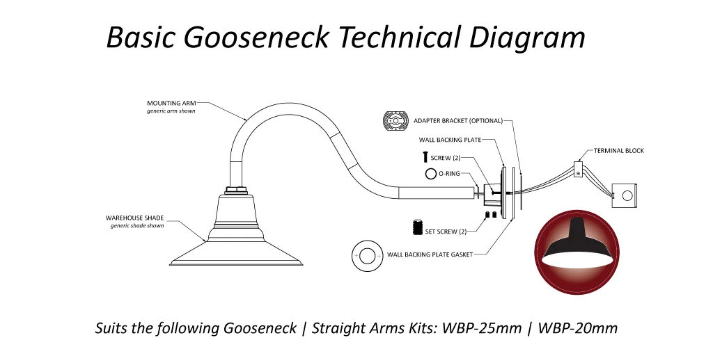
By now you should have:
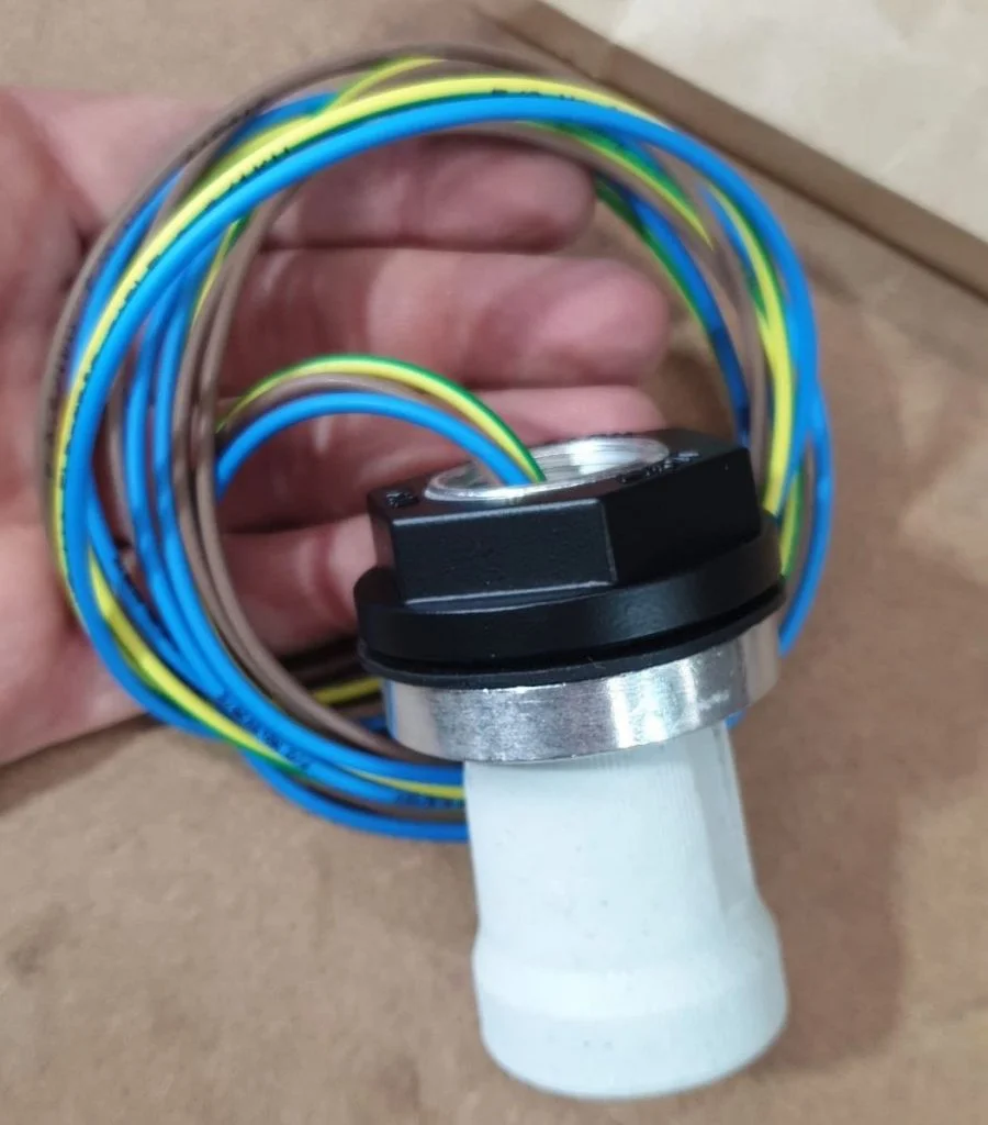
(A) A Standard Electrical Assembly – see below
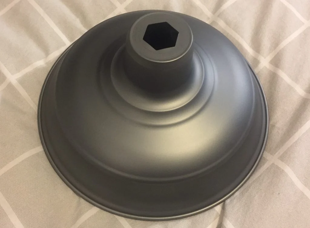
(B) Your Barn Light shade (Original, Old Dixie, Astro etc.)
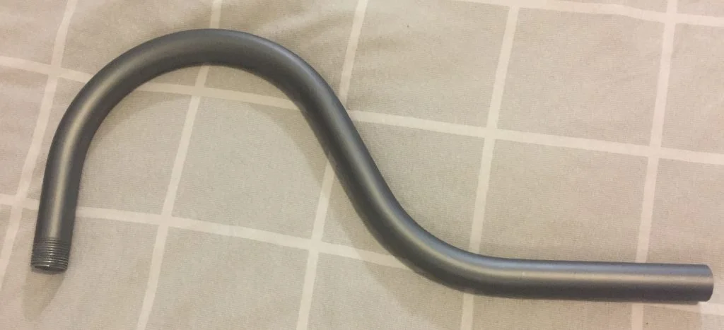
(C) A mounting arm (Gooseneck or pole arm)
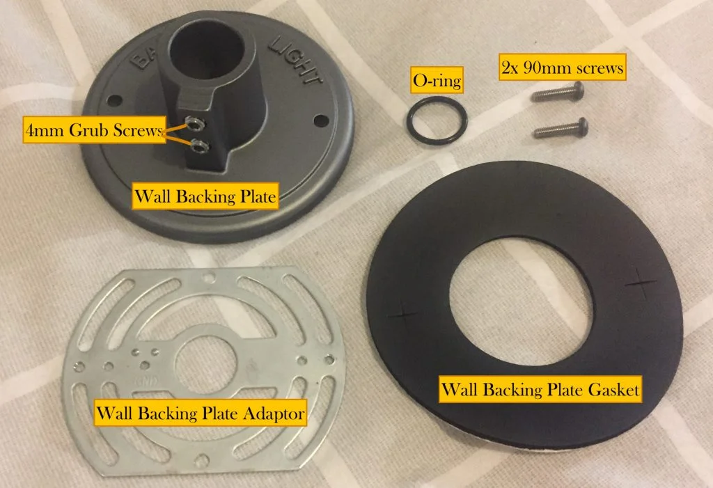
(D) A Wall Backing Plate Kit (plates, O-ring, gasket, brackets, screws – see below)
And optionally (E) Any guards or glass features you may have ordered including Atomic or Schoolhouse fixtures.
Also have ready some Silicone Thread Tape, a 4mm Allen Key, a thin flathead screwdriver, a marking pen, a drill, a Philipshead screwdriver and extra screws as needed.

Standard Electrical Array 
Barn Light shade (Old Dixie) 
Gooseneck mount 
Wall mount kit
Step 1: Be a qualified and licenced electrician.
Step 2: Disconnect the power both at the switch and the mains electrical panel before proceeding any further.
Step 3: (If you haven’t already) Cut a hole in the wall where you want to mount your Barn Light and extract the three wires: Active, Neutral and Earth. Attach them to a Terminal Block (you can remove and use the one at the end of the Standard Electrical Array).

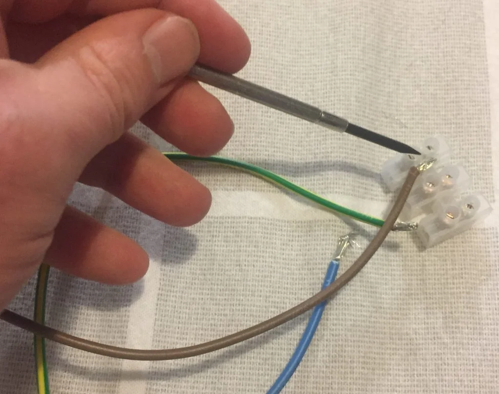
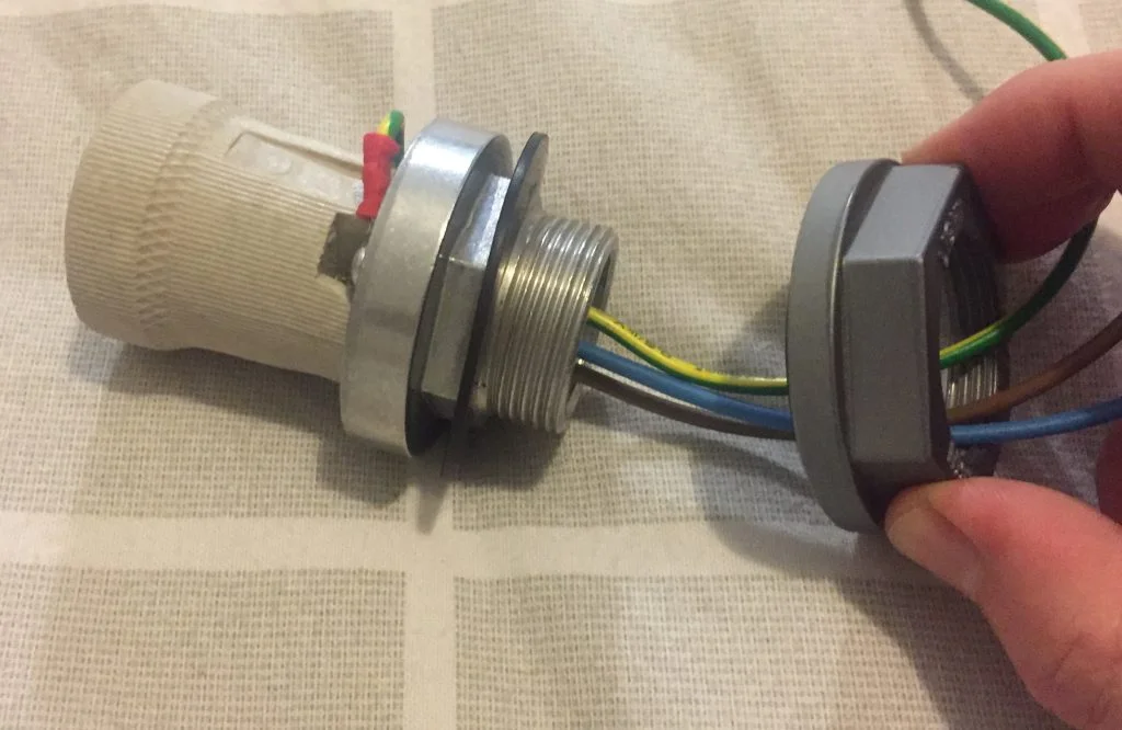
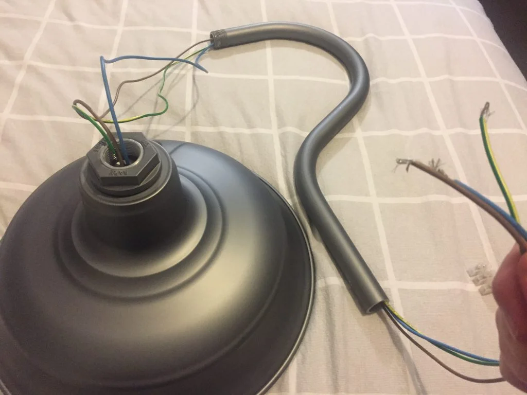
Step 4: Take the Standard Electrical Array. Remove the Terminal Block. Rotating CLOCKWISE (it is reverse threaded), unscrew the hexagonal Female Coupler stamped ‘Barn Light USA’, taking with it the large rubber O-ring (recessed in the Female Coupler) and leaving behind both the small rubber o-ring (inside the bolt of the Male Coupler) and the large flat rubber gasket on the Male Coupler. Remove the Female Coupler from the wires completely.

Detach Terminal Block 
Unscrew (Counter CW) and Remove Female Coupler
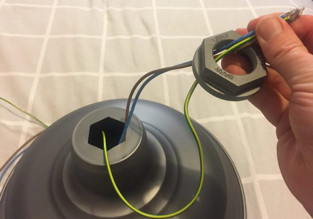
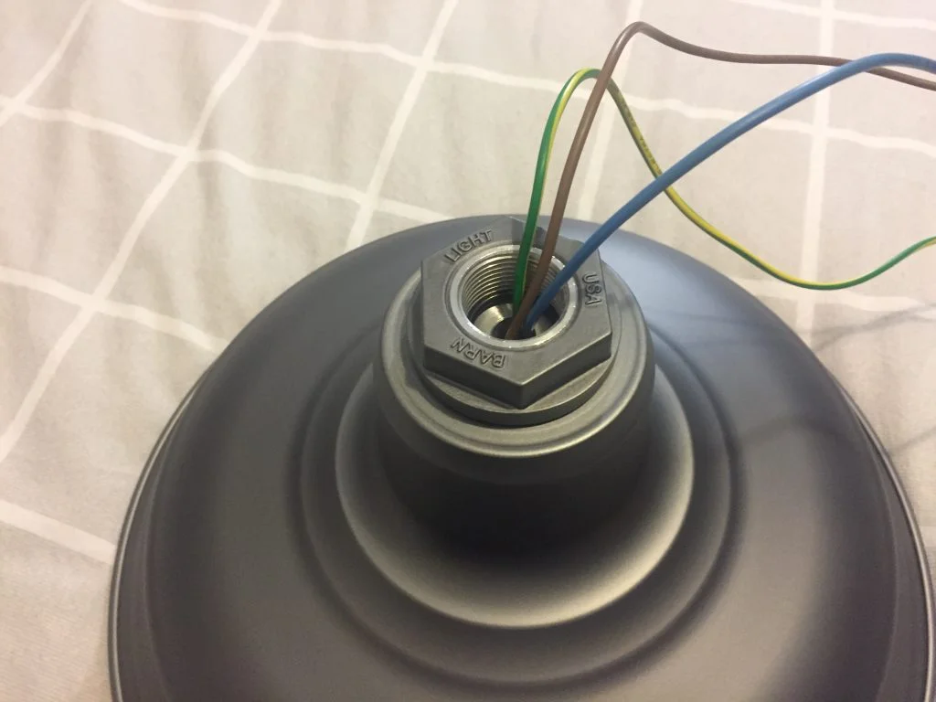
Step 5: Take your Barn Light shade and thread the wires from the Standard Electrical Array through the shade from the bell side until you can fit it on the hexagonal Male Coupler. Also thread the wires through the Female Coupler to meet the Male Coupler and screw them together COUNTERCLOCKWISE until they are a tight fit – Male Coupler (with O-ring inside), Rubber Gasket, Shade, Female Coupler (with O-ring embedded).

Thread wires through shade and Fem Coupler 
Pull Male Coupler through Hex and bolt to Fem Coupler
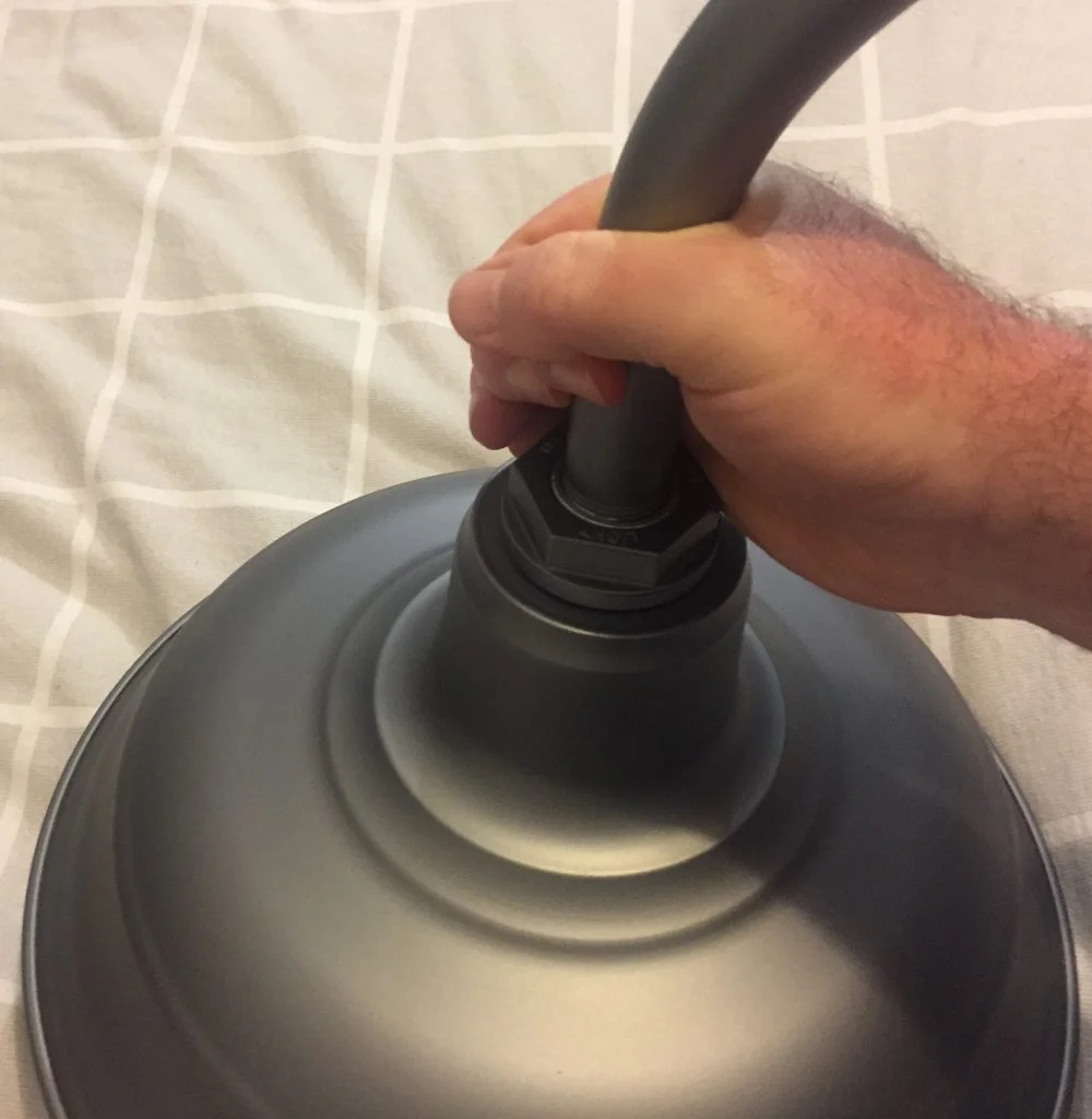
Step 6: Thread the three wires from the Standard Electrical Assembly, thread it through the Gooseneck from the non-wall end. Apply Silicone Thread Tape to the thread and screw the Gooseneck into the Female Coupler until tight.

Thread wires through Gooseneck 
Apply sealant to thread, then screw in until tight
Step 7: NB: Using the Wall Backing Plate Adaptor is preferable, and often useful on uneven surfaces, but not always possible. Skip 7a as necessary.
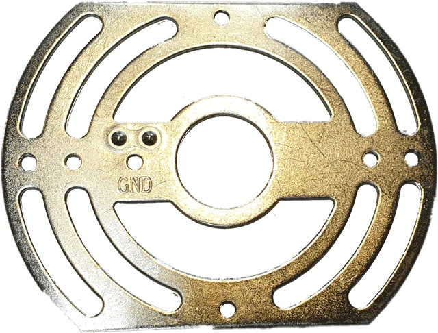
7a (optional): Place the Wall Backing Plate Adaptor level horizontally across the hole in the wall and mark the surface through the screw holes. The four holes on the inner circle will be to secure this Adaptor to the wall and adjust, and the two holes on the outer circle will be to secure the Wall Backing Plate (Step 9). Mark and drill holes as necessary, then secure and adjust the adapter to create a sturdy base flush with the wall.
7b (otherwise): If not using the Wall Backing Plate Adaptor, hold the Wall Backing Plate Gasket with the screw holes level across the hole in the wall, mark through the screw holes and drill as necessary.
Step 8: Peel the protective tape off the adhesive surface of the Wall Backing Plate Gasket and affix the gasket so that the Gasket’s screw holes line up with the two outermost screw holes on the Wall Backing Plate Adaptor (or with the holes on the wall directly if the Adaptor is not used).
Step 9: Take the wires that you have threaded through the gooseneck, and thread them through the metal Base Plate (stamped with Barn Light USA on the front) front to back.
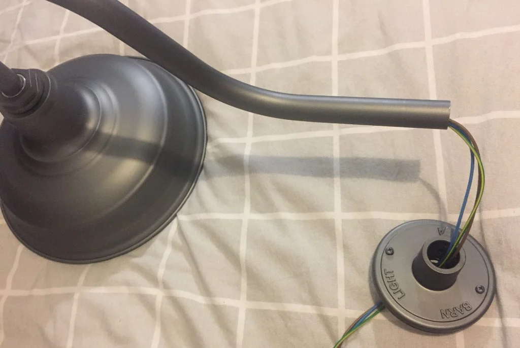
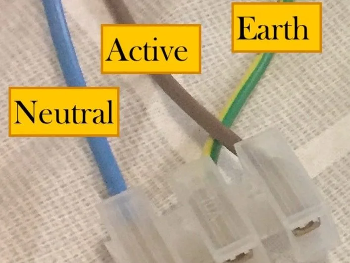
Step 10: Connect these to the Terminal Block in the wall colour-to-colour so that you connect:
The ACTIVE wires: Brown or Red
The NEUTRAL wires: Blue or Black
The EARTH wires: Green & Yellow
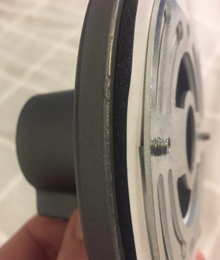
Step 11: Line up the Wall Backing Plate with the Wall Backing Plate Gasket so the screw holes line up. Screw them in using the screws provided.
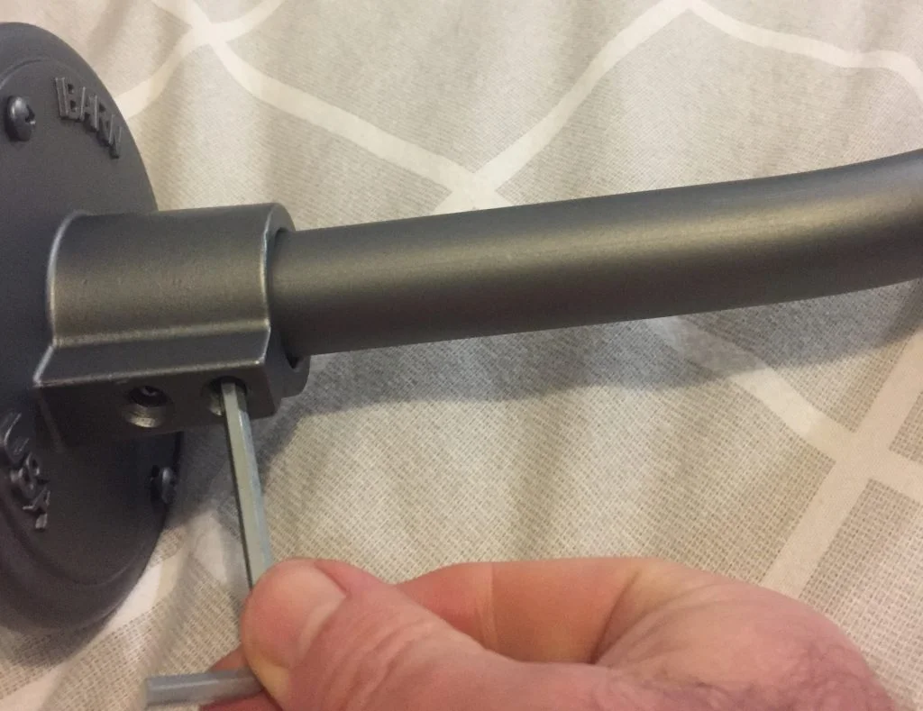
Step 12: Insert the small o-ring into the base plate, then insert the gooseneck arm and tighten it with a 4mm Allen Key using the two Set Screws beneath the stem on the Base Plate.
Step 13: Screw and tighten the whole array, adding a bulb, cages and glass as per your order.
Step 14: Turn on the electricity, switch on the light and admire your beautiful new Barn Light.
BAG / BOX contents
ELEC-25MM (OR ELEC-20MM) – STANDARD ELECTRICAL ASSEMBLY
What it looks like: A 25mm Hex Coupler w/ E27 (Screw) Ceramic Lamp-holder in a plain paper bag, made up of:
- 1x Ceramic E27 Lamp-holder
- 1x Male [Hex Coupler] base with female 3/4″ NPT threads* & Male External Threads
- 1x Female die-cast [Hexagonal Coupler] with “BARN LIGHT USA” stamped
- 1x Black neoprene [Hex Gasket]
- 1x Small O-Ring (BUNA-117*) recessed into the male coupler
- 1x Large O-Ring (BUNA-132) recessed into Die Cast Female Coupler
- 3x 0.75mm Electrical Cables (Brown/Blue/Green|Yellow)
*National Pipe Tapered Thread, commonly referred to as Plumbers Thread.
WBP-25MM (OR WBP-20MM) – WALL BACKING PLATE KIT
What it looks like: A standard Wall Backing Plate Kit in a long plain paper bag.
- 1x Female Die-Cast [Wall Backing Plate/WBP] stamped with “BARN LIGHT USA”
- 1x Steel Stamped Bracket [Adaptor Bracket] with multiple 8-32x threads
- 1x Black Small O-Ring (BUNA-117*) recessed into WBP
- 2x Philips Pan-Head Screws (8-32 x 3/4″) recessed into WBP
- 1x Large Closed Cell [Wall Backing Plate Gasket]
- 2x Grub Screws (5/16″ UNC x 1/2″) – Requires a 5/32″ or 4mm Hex Allen Key
*20mm Electrical & WBP Assemblies use a BUNA-115 O-Ring
WAREHOUSE SHADE OR ATOMIC FITTING
What it looks like: A standard warehouse, atomic, or schoolhouse fitting – All products with “HEX” hole. Normally the largest part in the box.
- Any of our standard Warehouse shades.
- ie. Original / Old Dixie / Eclipse / Astro
- Any of our standard ATOMic fittings
- ie. Atomic Warehouse / Atomic Flared / Atomic Industrial
- Any of our Schoolhouse Gooseneck series of product.
- ie. Schoolhouse Gooseneck
GOOSENECK OR STRAIGHT ARM – THE MOUNTING ARM
What it looks like: A piece of 25mm or 20mm Aluminium Extrusion straight or bent into a shape (Gooseneck) wrapped in brown paper
INSTALLATION INSTRUCTIONS
Doing your own electrical DIY may look easy, but it isn’t. It takes years for someone to qualify as an electrician to do electrical work around your home. It isn’t a job for a handyman. You could kill or injure yourself, your family, or start a fire….
ENERGY SAFE VICTORIA
Starting with ELEC-25MM (or ELEC-20mm) & Warehouse Shade
- Remove the Female Hex-Coupler by turning clockwise (Left-Handed Thread)
- Remove off the Male Hex Coupler Base entirely.
- Remove the Large O-Ring (BUNA-132), if loose reseat under Female Hex Coupler
- Feed 3x 0.75 Electrical wires inside the shade’s hex hole
- Push Male Hex Base flush with Warehouse Shade internal hex hole.
- Feed the electrical wires through the O-Ring & Female Hex Coupler.
- Tighten (Counter-Clockwise) the Female Hex Coupler onto Male Coupler Base
- Shade & Assembly Electrical Assembly is now complete.
Affix Warehouse Shade to Mounting Arm (Gooseneck/Straight Arm).
If the mounting arm is threaded.
- Apply Silicon Thread Tape to the mounting arm.
- Hold product in left hand, rotate thread Clockwise to affix thread tape correctly.
- Feed the 0.75mm Electrical Wires through the mounting arm.
- Rotate the counter-clockwise a few rotations (3-4 Max) with wires inside the mounting arm.
- Application of silicon compound into the male coupler base improves water resistance.
- Rotate the shade (Clockwise) to tighten the mounting arm. Rotate until resistance is felt.
- Gooseneck, Shade & Electrical Assembly is now complete.
If the mounting arm is not threaded – You’ll have received a 25mm or 20mm Nipple.
- Apply Silicon Thread Tape to the supplied nipple (3/4″ or 1/2″)
- Insert into Hex Coupler Base (BUNA-17 Seated) clockwise until resistance is met.
- Repeat the steps under “If the mounting arm is threaded”
- Close the small Grub Screw using a 5/64″ or 2mm Hex Allen Key on the mounting arm
- Straight Arm, Shade, & Electrical Assembly is now complete.
Affix Warehouse Shade to WALL BACKING PLATE
- Insert tail-end of the Mounting Arm into Wall Backing Plate – Ensure Small O-Ring is present.
- Apply Silicon Compound to WBP to improve ingress protection if desired
- Using a 5/32″ or 4mm Allen Hex Key – Tighten Grub Screws against the gooseneck.
- It is normal for grub screw impressions to be visible upon delivery.
We commonly take photos insitu of stock we sell at times.
- It is normal for grub screw impressions to be visible upon delivery.
AFFIX WALL BACKING PLATE TO STRUCTURE
The Standard Installation suggests the Wall Backing Plate be “face up” with “BARN LIGHT” at the top and centre of the wall backing plate. Some customers prefer a “side” mounting to improve wind resistance – These instructions are as if “BARN LIGHT” is top-centre.
WALL BACKING PLATE ADAPTOR
You’ll need to provide the correct fixings for the mounting surface, in some cases the adaptor bracket may not be of use. Please remember the Adaptor Bracket is OPTIONAL based on the mounting surface and water ingress prevention.

OVERALL WIDTH: 102mm
OVERALL HEIGHT: 78mm
SPACE BETWEEN MOUNTING HOLES:
90mm (Outer) – Goosenecks
70mm (Inner) – Stems
If the mounting surface is uneven, insert a screw (8-32 OR M4) at the bottom (or top) screw hole to produce an adjustable counter ever/fulcrum. Screw in/out to align centre to the structure before affixing Wall Backing Plate
- Every mounting is unique, thus these instructions are generic.
- Affix Adaptor Bracket (Long Left/Right, Short Top/Bottom) to mounting surface using required fixings (not supplied).
- ie Wood Screws for Timber | Concrete / Masonry Fasteners.
- Apply Wall Backing Plate Gasket to Adaptor Bracket ensuring the screw holes line up with with two most outer screw holes shown on the Adaptor Bracket (90mm)
- Pull supply wires through the centre hole and terminate electrical wiring using supplied Terminal Block or supply your own. The “GND” screw is additional at the discretion of the electrician to be used as a secondary earth. The lampholder holds the earth terminal leaving this secondary point somewhat redundant.
- Termination can be completed inside (recessed) or externally – Recessed is preferred*
- Screw 2x Pan Phillips Pan through the holes of the Wall Backing Plate and thread into Wall Backing Plate Adaptor
- It is normal for excess powdercoat to flake from the Wall Backing Plate once screws are affixed tightly.
*We have a “Heavy Duty Wall Backing Plate // HD-WBP” that can be used as electrical housing at additional cost. This housing will permit housing all electrical to be installed externally to the structure. Please be aware that these units don’t come pre-drilled, so be prepared to drill! Our Standard Wall Backing Plate (20 & 25mm) affix directly onto this backing plate.
